This was something I had created a while back, but because I was using it to develop another project, I decided to make a post about it. It is a simple PWM dimmer circuit that uses an Arduino Nano to read a potentiometer and PWM to drive a N-channel MOSFET.
Here is the circuit:
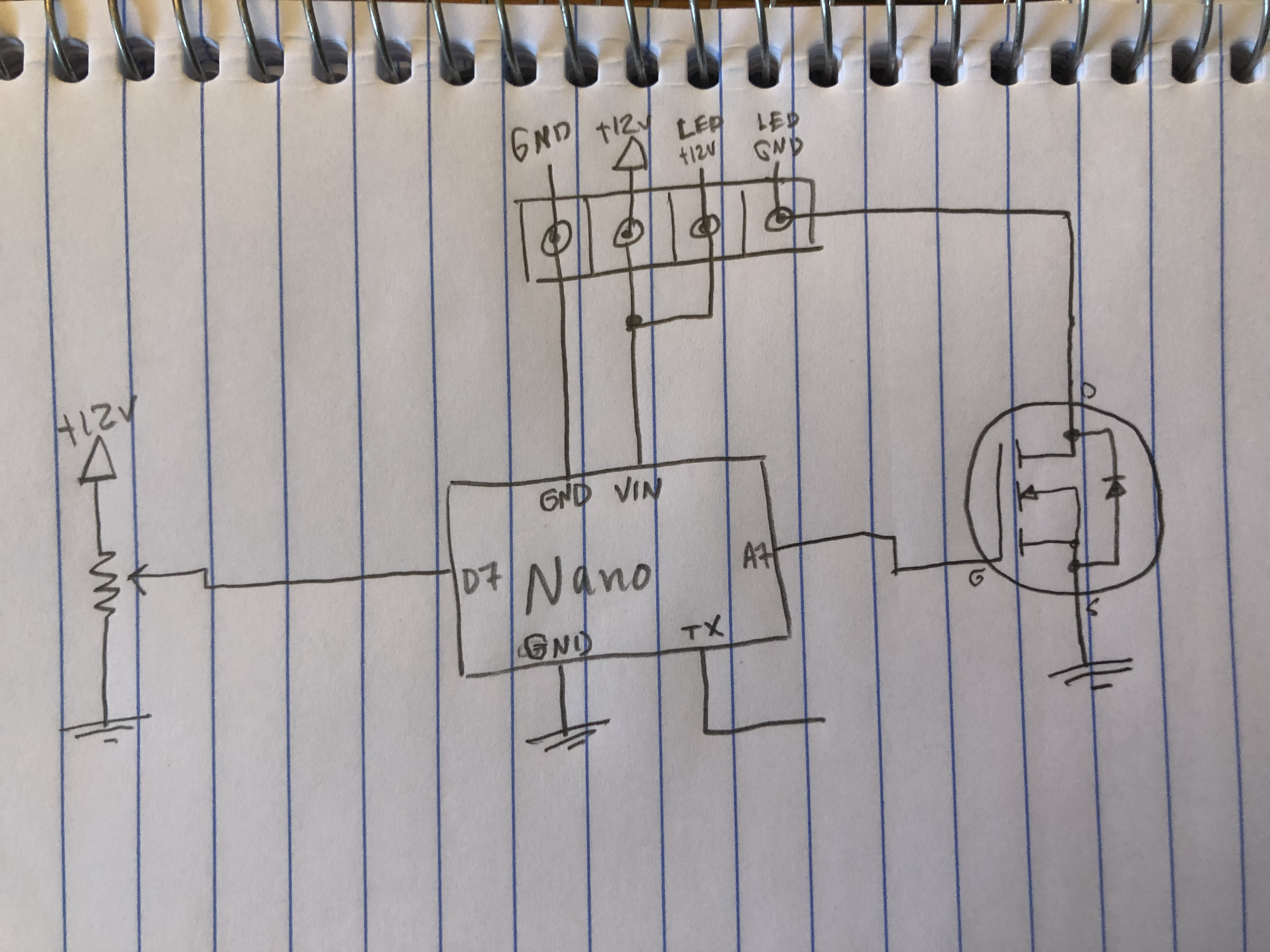
Super simple circuit here. There is a four position terminal block for input and output. The Nano’s VIN pin can take anywhere from 7V to 12V. The input voltage is fed back out to the LED. And the MOSFET is connected by PWM for low-side switching.
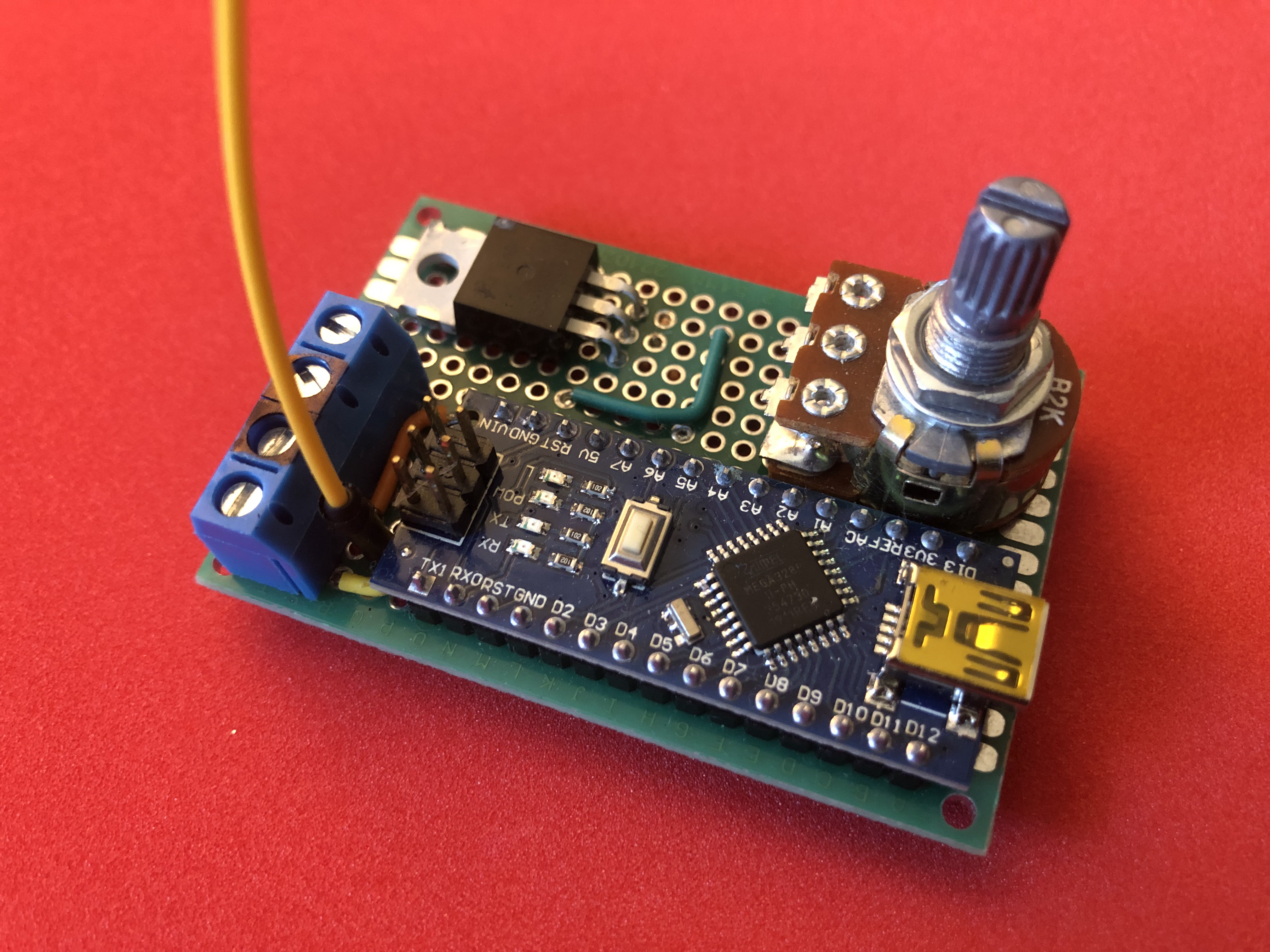
Here is a photo of the top side:
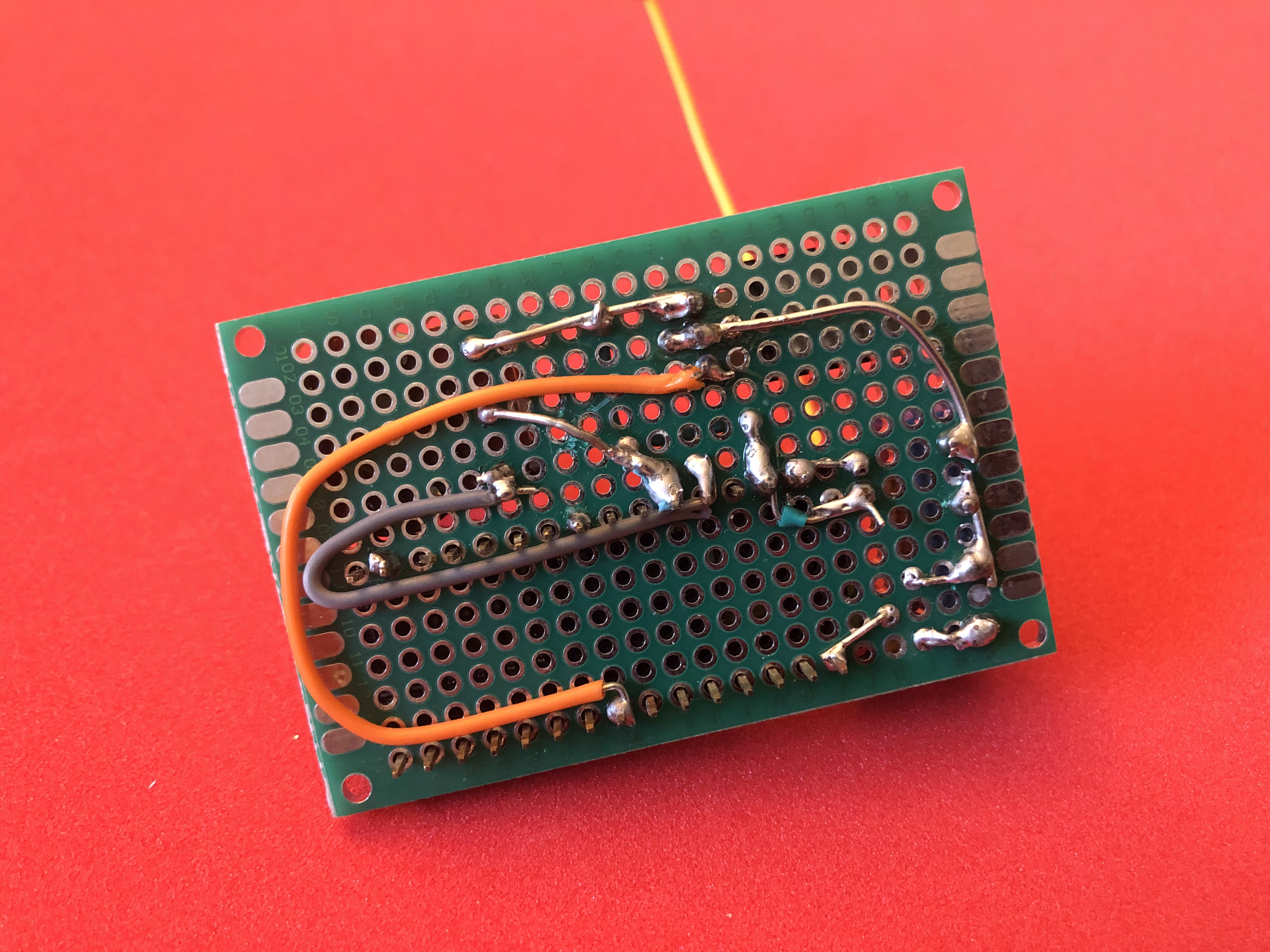
And a photo of the bottom:
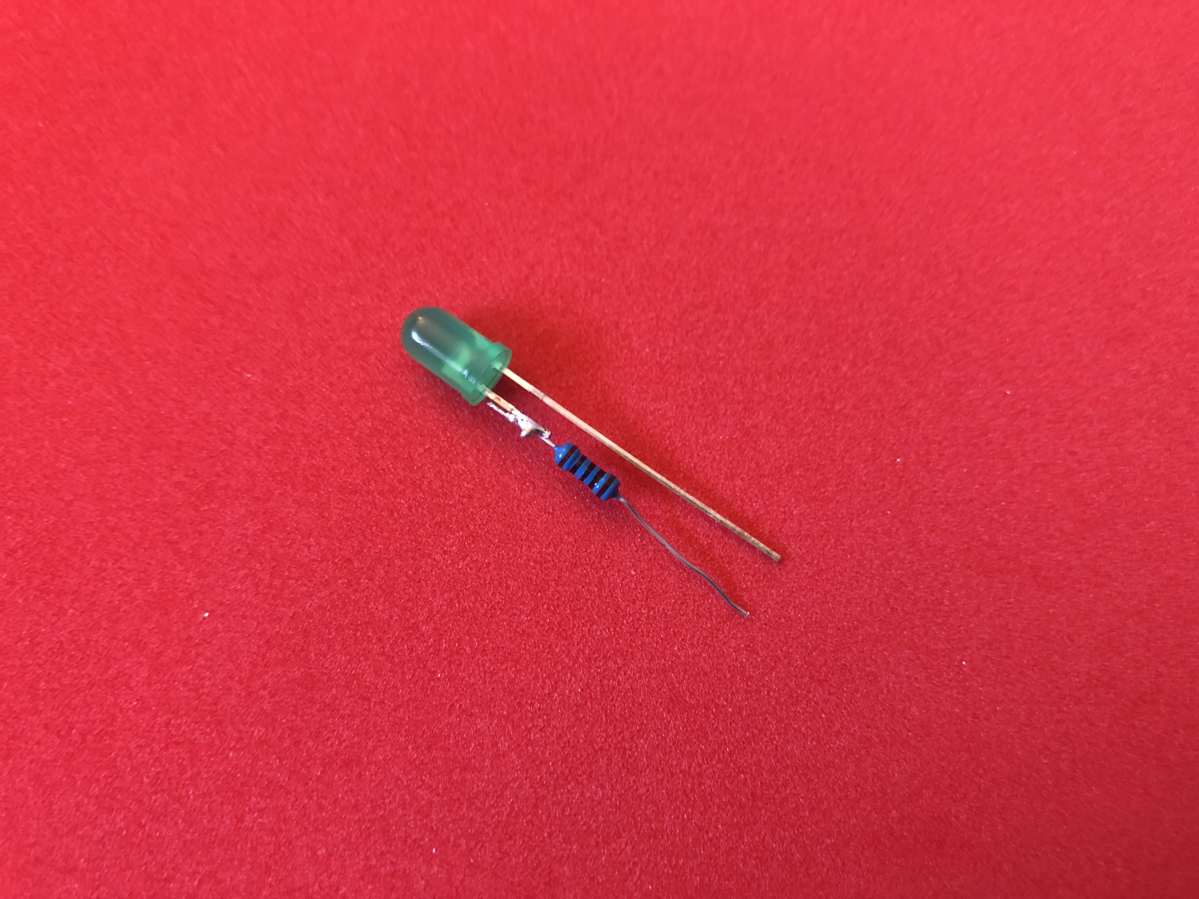
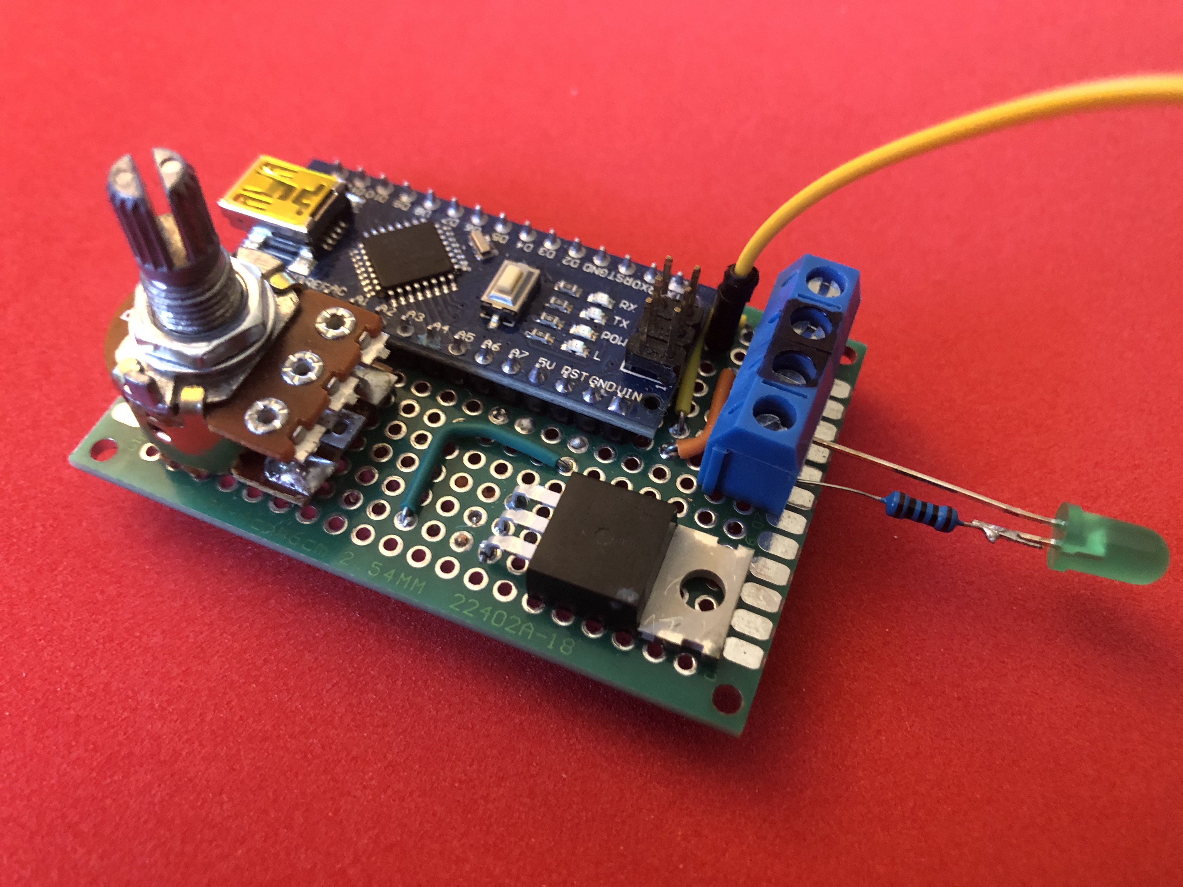
Now, when I first built this board, I had a 76mm LED Ring Light from Adafruit (https://www.adafruit.com/product/4433), which worked. But now I was using this board to test UART for something new I am working on, so I didn’t need such a bright light. Plus if something went wrong, I didn’t want to risk the light, so I used a cheap LED and 200 ohm resistor:
Here is a video I shot of the board in action. Sorry, the screen is so far away, you’ll have a hard time seeing plot trace.
Please check out my recent posts to the right and thanks for following along!