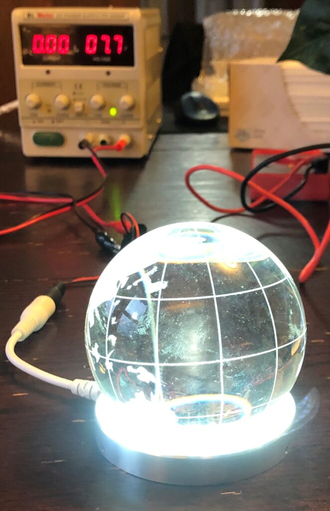
I’ve made a post with a PWM dimmer circuit used to control a N-channel MOSFET, (LED PWM Dimmer), and wanted to use it to control a high power LED ring I’ve had laying around for too long. The circuit is simple with a single ADC input and a single PWM output. Instead of having a potentiometer control the brightness, I wanted to have a photoresistor detect how much light was in the room, and adjust the brightness accordingly. The idea is to set a designed minimum and maximum brightness for any given time of day, and the darker the room becomes, the brighter the LED. The photoresistor will be located close enough to ‘see’ the LED light it is controlling, thus the LED will only become as bight as the maximum designed brightness level through a feedback loop.
Let’s take look at the schematic:
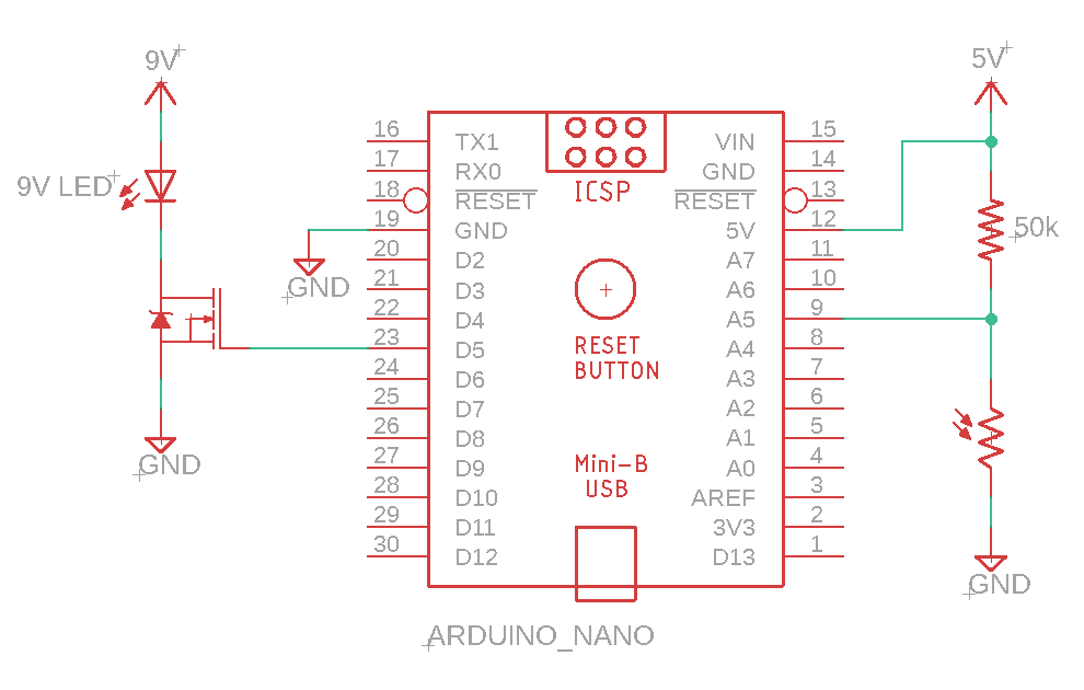
The D5 pin is connected to the gate of the low side MOSFET switch. All Arduino Nano’s pins are 490Hz except for pins D5 and D6, which are 980Hz. Doubling the update rate will help when the LED is dim, and the off period is more noticeable.
The A5 pin is connected to a voltage divider between a 50k resistor and the photoresistor. For the prototype I used a potentiometer so I could adjust the voltage divider while the circuit is powered up. I measured the photoresistor’s resistance at a normal ambient room light level, which gave the reading of 50k, hence the value for the fixed resistor. With 5V applied to the fix resistor, and the photoresistor’s connect to ground, A5 should read roughly 2.5V. If the room is brightly lit, the resistance of the photoresistor drops, causing the voltage on pin A5 to drop.
The Arduino Nano analog input pins have a 10 bit resolution, while the Arduino Nano PWM use 8 bit. To convert the reading from 10 bit to 8 bit, we could just capture the eight most significant bits, we could cross-multiple-divide, or we could use the built in function Map. Map takes five datatype ‘Long’ arguments and returns a datatype ‘Long’ value.
long map(long x, long in_min, long in_max, long out_min, long out_max) {
  return (x - in_min) * (out_max - out_min) / (in_max - in_min) + out_min;
}
This would be a good application for a windowed ADC reading. Most of the readings from the ADC will be at or below a certain reading because at night the sensor reading will be higher causing the PWMs value to increase. If the maximum desired brightness is 180 out of a possible 256, then 31% will never get used. And I will want it to remain dim during the day, so if the minimum desired brightness is 60, so another 23%. Setting those upper and lower limits for the ADC will mean higher resolution for just the voltage range we are using.
Putting it all together, you’ll see that if I move my finger over the sensor, the LED will be come dimmer. Of course I needed to dial in the minimum and maximum values so that when the 10 bit ADC tries to overflow the 8 bit PWM. You’ll see the circuit is trying to go beyond 255, causing it to roll over and starting counting up from zero.
Now that I have a good proof of concept, I and begin to design a custom PCB and choosing which enclosure to package it all.
Thank you for following along! Be sure to check out my other posts!