Continuation of the posts Breadboarded: Hydro Controller Prototype and Coded: Hydro Controller Prototype.
To make the breadboarded circuit easier to work with, I transferred it over to a protoboard. Once the circuit was tested, I grabbed a protoboard and some pin headers.
Parts list:
- 7cm x 9 cm Double Sided PCB Board
- 2.54″ Female headers
- Breadboard jumper wire
Because of the headers lifting the ESP32 up and off of the PCB, I was able to run connections underneath it. And while mapping out how I was to connect everything together, I considered if swapping pins that could do that same functions to make it as simple as possible to implement.


There was a game for my phone called Flow (https://apps.apple.com/us/app/flow-free/id526641427) that was a lot fun, and also I seemed to have a knack for and could do some of the puzzles in the later stages in one attempt. Which reminds me of the circuit in the photos above. I seemed to get really lucky in terms of not having to cross wires over each other.
I like using breadboard jumper wires like these for prototyping because the wires are pretrimmed and are very flexible. And they are insulated, so I have to spend less time worrying about unused pads accidentally connecting two nets together.
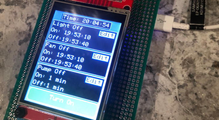
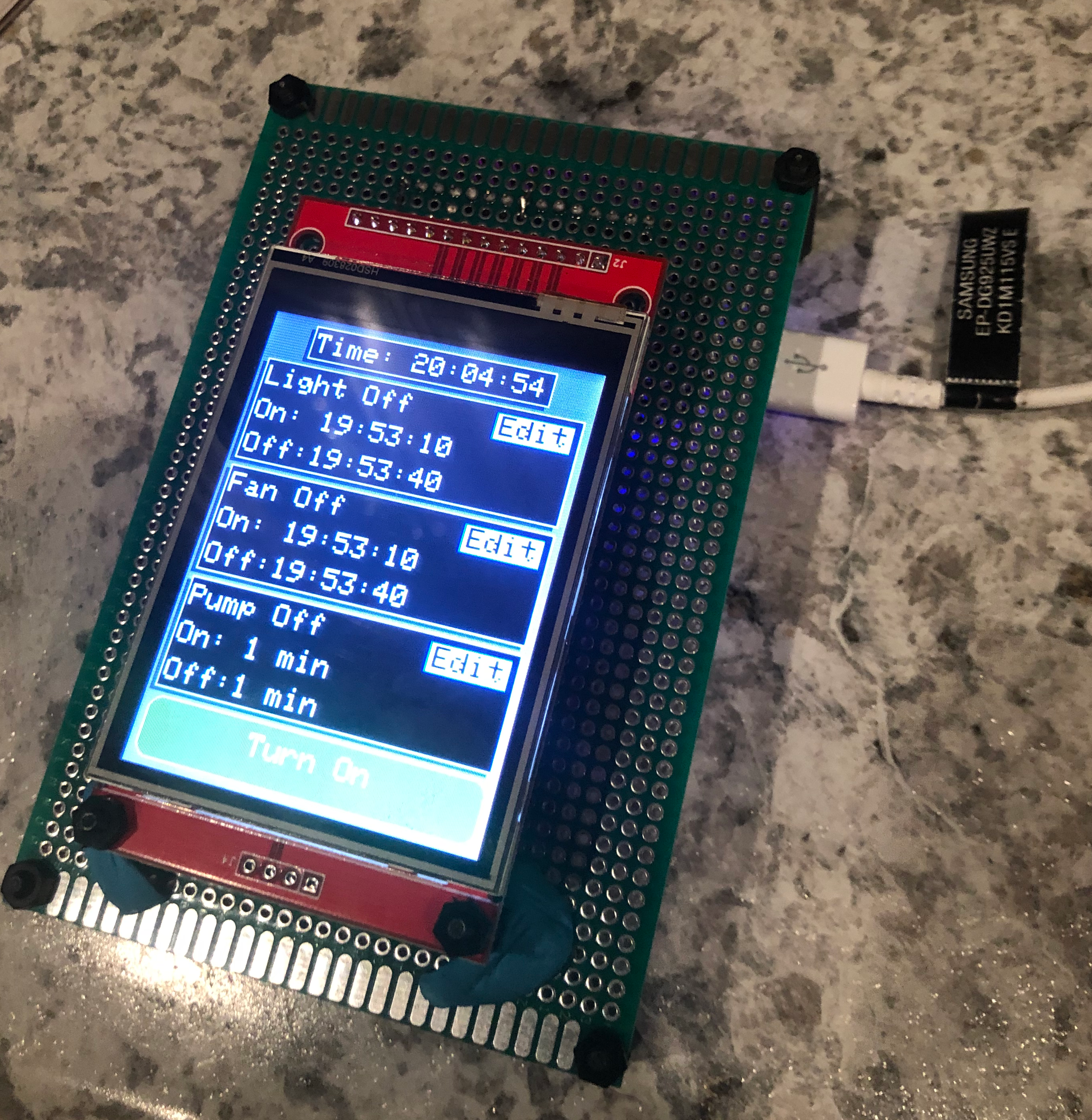
After continuity testing the solder joints to verify I didn’t have any solder bridges, I plugged in each component:
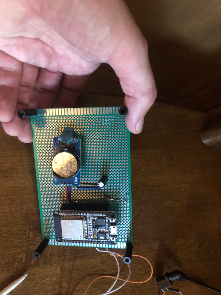
I added a push button to initiate a hard reset causing the system to run the calibration upon reset and resetting stored time values in SPIFFS to default values. That function can also be called in software. Ideally each component will have their own reset function which can be called to re-initialize each one individually. For one after another for a full reset.
One end of the TFT had the pin headers while the other end had nylon standoffs just about as tall as the pin headers, so it made for a good firm surface for the touchscreen.
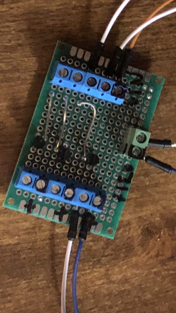
Two things I didn’t add to the design was a terminal block for connecting the output lines to the relay card, and a transistor stage to switch on and off another power rail. To temporarily solve the connection with the output, I just solder jumper wires to the ESP32 pins. For the transistor stage, I built a separate circuit with three channels, one for each Light, Pump, and Fan. I used the 2N3904 NPN BJT, which has the maximum Emitter-Base voltage rating of 6VDC, which was well above the 3.3VDC the EPS32 GPIO puts out. And a maximum Collector-Emitter voltage rating of 60VDC, which was well above the 12VDC I was planning to use to activate the relay’s coil.
According to the datasheet for the relay that was used, the coil draws 111mA. Which is just over half the transistor’s maximum Collector’s continuations current draw of 200mA. And I know I’ve been referring to the maximum ratings of the BJT, which are outside of the operating characteristics. But I wasn’t concerned about rise or fall times, or minimum switching on or off voltages. As along as I didn’t approach the maximum ratings, I felt safe for a prototype demo. If I burnt the BJTs, I could easily swap out the BJT for MOSFETs.
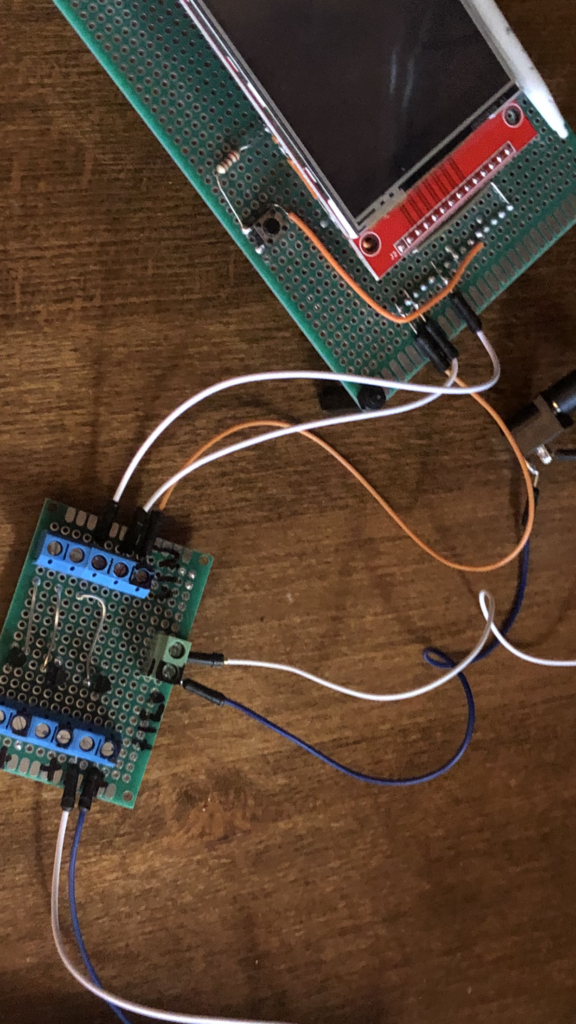
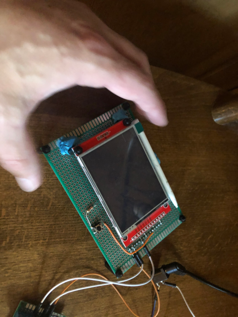
And a test to make sure it worked. I left it running for quite a while without anything getting to warm to the touch.
Because this was EE focus post, I’ll follow this post up with a SE component to further dive into the code that drives the screen, controls the outputs, and does a whole bunch of housekeeping for getting things up and running. Please check out my recent posts to the right and thanks for following along!