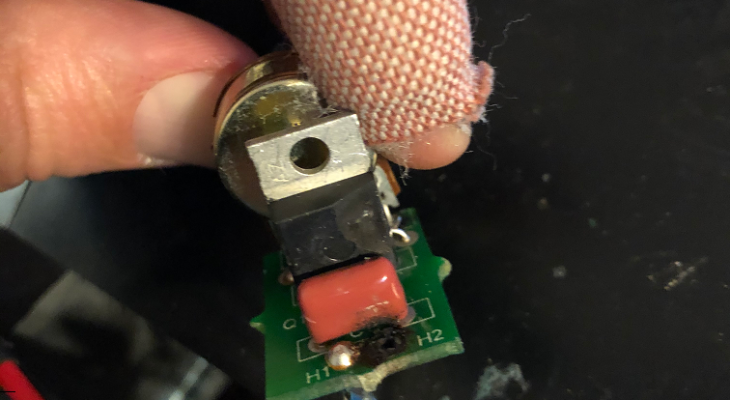
I once met someone that tried to solder while the circuit board was still in place; and plugged in. He accidentally touched the metal case with the soldering iron and heard a loud bang.
He asked me if I would take a look and I saw a blown PCB trace and a TO-220 packaged integrated circuit with a chuck missing.
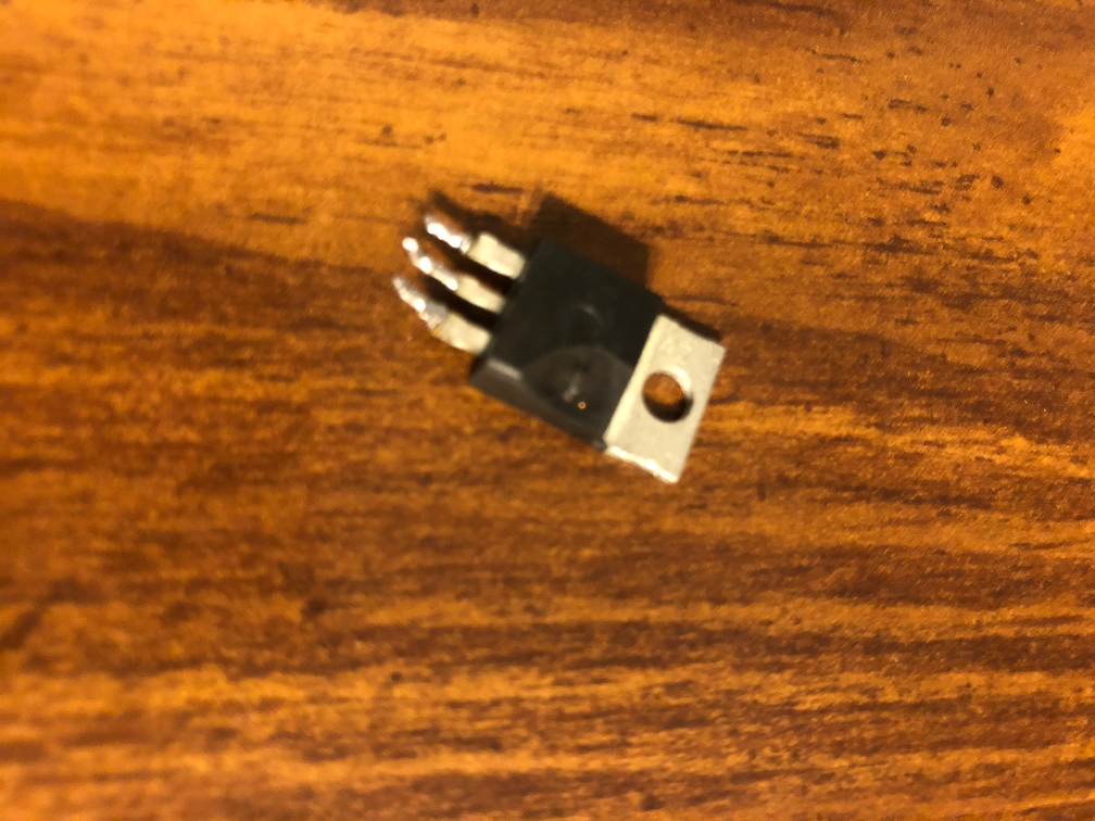
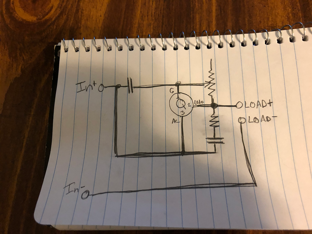
Looking on the internet for racket tension machine circuits, I see it that is a triac, commonly used for motor speed control. When the voltage applied to the gate is above a certain threshold, the other two pins begin to conduct, and continue to conduct until the voltage across them returns to 0v, even if the voltage on the gate has been removed. And because it is bidirectional, it will even work when the voltage applied to the gate is negative. The potentiometer adjusts the bottom half of the voltage divider between the “output” pin and the gate. This allows the “output” to turn on later in the phase for PWM effect. So the potentiometer is used to delay the gate from turning on, thus limiting the time current is flowing.
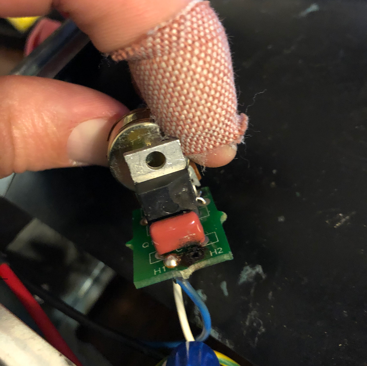
After pulling it out, I mapped out the circuit on the PCB. It consisted of the triac, two capacitors, a resistor, and 10k potentiometer. Let’s take a look at the circuit diagram:
Looking on Mouser for a triac that could handle the load rated on the the motor and didn’t have the gate be the middle pin, I told my friend to order it, and it would fit right in to the existing location. I was happy to hear from him that is work perfectly.
Please check out my recent posts to the right and thanks for following along!