For my final group project in Engineering programming at Portland State University, we were tasked to create a counter on a 7 segment display. Even though the course was on C programming, we were allowed to use Arduino. I did need to keep the code beginner friendly due to the other group members being new to programming. But since I just needed to know the difference between C and C++, I took the “diagnostic” requirement the extra mile, and created a GUI interface using Processing to test the display.
First things first! How does this display work? I connected my power supply’s positive power lead to the L1 pin, and through a 220 ohm resistor, connected my negative lead to one of the A through Dp pins. In the image below, it happened to be the B pin. Then slowly turning up the voltage on the power supply to 3.3v and I saw the segment LED turn on. If it didn’t light up the first time, I would just switch the leads.

Alright, now to add more resistors to the rest of the cathodes, and hook up the Arduino Nano to all the pins and attempt to turn all the LED segments for a single digit.

Check! How about all of the digits?

NICE! One last test is to select a specific digit to light up by itself.

All set. Now to do some coding. The simplest way I could think of to create “digits” on the display was to create an char array with the first element in the array to hold the 1’s and 0’s for zero, and the second element would hold the 1’s and 0’s for one, and so on. The following is slightly modified for the sake of a simpler explanation, the full code linked the bottom will have what I demo’d for the final grade. Here is some code to create digits, as well as a few other lines to use later in the explanation:
/*
* === Making numbers that don't change human readable ===
*/
// Making pin numbers human readable
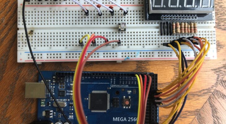
// We ended up using a Arduino Mega 2560,
// so the select line pins got moved to 50, 51, 52, and 53
#define selectA 50
#define selectB 51
#define selectC 52
#define selectD 53
/*
* === Creating our characters and select line arrays ===
*/
/* A
* F B
* G
* E C
* D Dp
*
*
* 8 7654321
* 0b(Dp)GFEDCBA
*
*/
// D
// pGFEDCBA
const char characters[16]= { 0b11000000, //0
0b11111001, //1
0b10100100, //2
0b10110000, //3
0b10011001, //4
0b10010010, //5
0b10000010, //6
0b11111000, //7
0b10000000, //8
0b10010000, //9
0b10001000, //A
0b10000011, //B
0b11000110, //C
0b10100001, //D
0b10000110, //E
0b10001110 //F
};
const char displays[] = { selectA,
selectB,
selectC,
selectD };How is this useful? “AVR® 8-bit microcontrollers control applications through their digital Input and Output (I/O) pins. These pins can monitor any voltage present as a high impedance input and supply or sink current as a high or low voltage digital output. These pins are usually organized in groups of eight and referred to as a port. The AVR uses the alphabet to name these ports, for example: PortA, PortB, etc. The pins of PortA are referred to as PA0 – PA7.” (https://microchipdeveloper.com/8avr:ioports)
I have the Nano’s microcontroller’s (ATMEGA328P) PortC output pins connected to the display so that the PC0 pin controls the ‘A’ LED segment, and PC1 pin controls the ‘B’ LED segment, and so forth. See above code snippet for arrangement of A, B, C, D, E, F, G, and D(ecimal) P(oint) LED segments.
This is done for the purpose of speed. If the LED segments were connected to different ports, we would need to set each output pin separately:
char lower_nibble = 0b1101;
char upper_nibble = 0b0000;

// If bits 4 through 7 were connected to the lower nibble of Port C:
PORTC |= lower_nibble;

// and bits 0 through 4 were connected to upper nibble of Port A:
PORTA |= (upper_nibble << 4);

// It would still be two calls
The problem gets even worse if we use Arduino digitalWrite() function. Here is an example of how the digit ‘3’ would be set:
digitalWrite(2, HIGH);
digitalWrite(3, LOW);
digitalWrite(4, HIGH);
digitalWrite(5, HIGH);
digitalWrite(6, LOW);
digitalWrite(7, LOW);
digitalWrite(8, LOW);
digitalWrite(9, LOW);
It doesn’t look too bad, but calling the digitalWrite function takes quite a bit of time. Let me show you how to do that in one statement if we are only using pins attached to PortC:
PORTC = 0b10110000;Not only is it less code to write, but that one assignment takes less time than a single digitalWrite call.
Now, we want all our digits on the display to start off as ‘0’, so will need to create variables to hold the 1’s and 0’s for each digit, as well as variables to hold the numerical value of that digit.
Then we can create an array to hold the char arrays for our digits.
char ones, tens, hundreds, thousands;
int i_ones, i_tens, i_hundreds, i_thousands;

void setup() {
    i_ones = 0;
    i_tens= 0;
    i_hundreds= 0;
    i_thousands= 0;
    ones = characters[i_ones];
    tens = characters[i_tens];
    hundreds = characters[i_hundreds];
    thousands = characters[i_thousands];

    const char digits[] = { ones,
                              tens,
                              hundreds,
                              thousands };
    ...
Now in the loop, we will just “pulse” each digit’s cathode pin, which I will refer to ‘select pin’ from now on. If you’ll look at the first snippet of code, you’ll see I have an array to hold the pin number for my select pins called ‘displays’. This way I can just loop over the array:
void loop() {
    for(char i = 0; i < 4; i++) {
        PORTC = digits[i];
        digitalWrite( displays[i], HIGH);
        digitalWrite( displays[i], LOW);
    }
    ...
Now the ‘for loop’ will set PORTC’s value and bring the select pin high and immediately low before moving on to the next digit on the display. At the end of the main program loop, it would just start over.
Leaving it here, the Arduino would load ‘0’s to all the digits on the display, and the main loop would just cycle through pulsing each one. And yes, it pulses each one and moves on the next and starts over again so quickly, they look to be on all at the same time.
Quick note on setting PORTC’s value. PORTC will be assigned to the value of digits[i], which can be shown to resolve to PORTC = 0b111110011 as shown here:
PORTC = digits[i]
which resolves to
PORTC = digits[0]
which resolves to
PORTC = characters[i_ones]
which resolves to
PORTC = characters[1]
which resolves to
PORTC = 0b11111001
Remember when we assigned a binary number to PORTC earlier?!? Go ahead, take a victory lap around the room.
Ok, now sit back down, we’re almost done.
So, since the assignment wasn’t just to show ‘0’s on the display. We want this to increment. Let’s add some code to the main loop that will increment the ‘ones’ digit.
i_ones++;Putting the code that increments ‘i_ones’ in the main loop will increment that number so fast, the digits on the display would just be a blur. All the segments would turn on and off so quickly, they would all just appear dim. The segments that are used more than others and would be turned on more often, and appear brighter, but not readable all the same.
To solve this, we will use the microcontroller’s timer peripheral. This is basically a stopwatch built-in to the microcontroller that get ignored until the stopwatch (timer) counts up to a predefined number, signals to the microcontroller, resets to zero, and starts to count up again.
Here is the code I basically copy and pasted from the ATMEGA328P’s datasheet that sets up the timer to signal the microcontroller at one second intervals:
// Good thing for datasheets and people smarter than I
void initTimer()
{
  // http://ww1.microchip.com/downloads/en/DeviceDoc/Atmel-7810-Automotive-Microcontrollers-ATmega328P_Datasheet.pdf
  char cSREG;
  cSREG = SREG;             // store SREG value
  cli();                    // disable all interrupts
  SREG = cSREG;             // restore SREG value (I-bit)

  TCCR1A = 0;               // Zero out the timer control
  TCCR1B = 0;               // registers

  TCNT1 = tick_rate;        // preload timer 65536-16MHz/256/1Hz
  TCCR1B |= (1 << CS12);    // 256 prescaler
  TIMSK1 |= (1 << TOIE1);   // enable timer overflow interrupt
  sei();                    // enable all interrupts
}
Explaining what is going on in the ‘initTimer’ function above is beyond the scope of this post, but if you call this function from the setup function, it will set everything up to call the interrupt vector ‘TIMER1_OVF_vect’. Interrupt is exactly what the name implies. It gets triggered, the microcontroller stops what it was doing, runs the code in the interrupt vector, and then goes back to what it was doing right before the interrupt was triggered.
What that means in a nutshell is, the function ‘TIMER1_OVF_vect’ gets called at one second intervals (in this example.) Quick note about interrupts, they need to be short as possible. Maybe something like this:
ISR(TIMER1_OVF_vect)
{
    i_ones++;
}
Now, once a second, the integer varable ‘i_ones’ gets incremented.
All there is to do now is to increment ‘i_tens’ after ‘i_ones’ is ‘9’ and is incremented.
Might just be easier to show the code:
if(i_ones > 9)
{
  i_ones = 0;
  i_tens++;
}
if(i_tens > 9)
{
  i_tens = 0;
  i_hundreds++;
}
if(i_hundreds > 9)
{
  i_hundreds = 0;
  i_thousands++;
}
if(i_thousands > 9)
{
  i_thousands = 0;
}
Extra credit reading: Taking this project an extra step further, I wrote a PC application that will send data over UART to the Arduino. There is also more code written in the Arduino to receive the data and do special “diagnostic” operations such as, decrement the counter, flash all segments for all digits, and even cycle through the segments, one at a time. Here is a video I recorded while doing testing. I can’t stress enough to record your testing sessions. If something happens while randomly and wildly clicking the mouse, you can review the tape. Here was one of the last records I did for this project:
Ok. I hope someone found this helpful. If you wanted to view the full code, follow the link below. There is a mix of another person’s code in with my code. He wasn’t able to make the team meetings and had to inject his code, so it might look out of place or redundant. But if you’ve gotten this far, you should be fine.
https://github.com/dpnebert/Clock/blob/master/MEGA2560_Clock.ino
Please check out my recent posts to the right and thanks for following along!